FREQUENCY RESPONSE
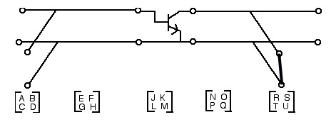
The shunt stubs and main lines are modeled as
ideal lossless, non-dispersive, TEM transmission line elements. The transistor
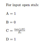
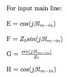
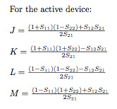
is modeled as the two port S parameter device. The shunt stubs can be chosen as "opens" or "shorts" in the program but have to be of the same kind for both stubs. Both types are depicted in the topology for reference only to the corresponding matrix. The matrix elements are all in terms of the corresponding chain parameters. The S parameters of the device are transformed
into the chain parameters for matrix manipulation. Matrix multiplication
proceeds progressively from the output port to the input port resulting in the
composite ABCD parameters. These are then transformed to the S parameter
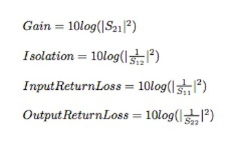
equivalents. The insertion gain, isolation, input return loss, and output
return loss are formulated from the S parameter relationships.
The electrical line lengths and S parameters are all functions of frequency.
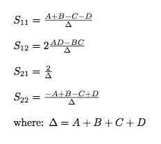
After the matrix multiplication routines are carried out the composite chain matrix elements are transformed back to S parameter representation by the following transformations:
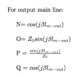
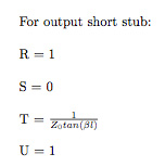
The following definitions for the output response functions apply:
For the lumped elements realizations the shunt stubs are replaced by the shunt connected susceptance while the main lines are replaced by the series connected reactance.
The matrix elements are then given by:
For input susceptance:
A = 1
B = 0
C = jbin
D = 1
For input reactance:
E = 1
F = jxin
G = 0
H = 1
For output susceptance:
N = 1
O = 0
P = jbout
Q = 1
For output reactance:
R = 1
S = jxout
T = 0
U = 1
Marcus Staloff
© 2013